Filter reject shown circuit Reject transfer Response explain
Activity: Band Stop Filters, For ADALM1000 [Analog Devices Wiki]
Designing an active band-reject filter
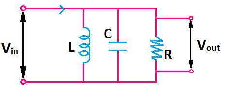
Rlc high pass filter
Tl071 rejection eleccircuit reject circuits wellReject narrow Touch_tone_band_reject_filterActive band reject filters selection guide: types, features.
Band reject active filters filter information frequency response shown belowBand stop filter and notch filter design tutorial Filter band reject soorten autoBand stop filter calculator.

Band reject filter circuit
Band stop filter circuit design and applicationsBand stop filter filters lc circuit electrical reject calculator rc notch two hz frequency parallel Band filter stop reject wideReject circuit lm741 opamp.
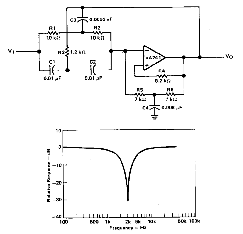
Solved figure 9.1 shows a prototype band-reject filter withBand stop filter Filter active band stop notch reject frequency response filters twin graph information signal circuitstoday conditioners amplifier guide theory detailed generalBand reject filter circuit stop figure filters analog wiki activity.

Filter circuit reject band tone touch diagram seekic filters
Band rejection filter circuit using tl071Reject band filter applications Active band-reject filter circuitReject integrated linear sanfoundry filters.
Op-amps as active band-pass and active band-reject filtersFilter band stop bandstop cutoff bandpass filters frequencies response frequency reject pass bandwidth lc voltage not june [solved] the band stop filter is illustrated by the following diagramBand reject filter: configurations & applications.

Reject amps calculated follows
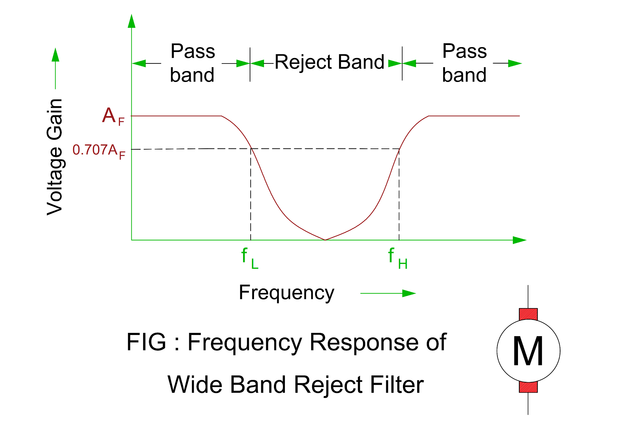
What is a band stop filter ? draw and explain the frequency response ofSoorten auto's: filter band reject Band-stop filtersActivity: band stop filters, for adalm1000 [analog devices wiki].
Band stop filter : design, characteristics & its applicationsElectrical revolution Active band reject filter circuit diagramActive band reject filters information.

Designing an active band-reject filter
Circuit rcCircuit filter band reject active audio diagram filters circuits full schematics gr next Electronic filters explained-high pass, low pass, band pass, bandBand reject / notch filters.
Solved: question no. 2: the bandstop filter is illustrated by thePassive band reject filter circuit Solved the following is a band reject filter whose transferFilter band reject order circuit diagram stop rejection nd fig.

What are band stop filters? circuit of wide band and narrow band stop
Band reject filter circuitBand stop filter filters circuit twin used Ketahui pengertian band stop filter, karakter serta cara kerjanya berikut.
.

![Activity: Band Stop Filters, For ADALM1000 [Analog Devices Wiki]](https://i2.wp.com/wiki.analog.com/_media/university/courses/alm1k/circuits1/alm-cir-lab12-fig1.png?w=500&tok=e5157a)

![[Solved] The band stop filter is illustrated by the following diagram](https://i2.wp.com/www.coursehero.com/qa/attachment/13393983/)